
At present, many bag filters are undergoing transformation, but many enterprises do not know the specific standard. The specific standard stipulated by the state is 30mg / m3, but many enterprises are defined as 15mg / m3, which is the test put forward for our bag filter enterprises, so how can we reach this standard? Based on years of experience, Note the following:
1. The opening of the flower board must be cut by laser, so the accuracy is relatively high. The dedusting bag must be made in combination with this size, without deviation. If there is deviation, it will cause the dedusting bag to fall off or there will be dust passing through the gap, which will affect the discharge standard of the bag deduster.
2. When the flower plate of the bag filter is welded, it must be smooth, flat and free of missing welding or gap. If possible, fluorescent powder or pressure test can be used, especially for the welds of the middle box and upper box of the bag filter, which must not leak.
3. The dust bag to be used shall be covered with film, because the size of dust particles allowed to pass through the retroperitoneal dust bag is only a few microns, and the slightly larger dust can not pass through at all. In addition, when designing the bag dust collector, it is necessary to control the wind speed of the dust collector, which can meet the dust emission requirements of 15mg when the wind speed is not more than 1m.
Simple air inlet device comparison
1 air inlet of ash hopper (1)
Some bag type dust collectors are designed as the down air inlet mode, i.e. air inlet from the ash hopper. This kind of air intake can save the floor area and steel consumption, but it is easy to cause problems such as high resistance of the equipment, the filter bag being scoured by the dusty air flow and so on.
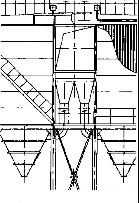
The picture shows a long bag low-pressure pulse bag type dust remover, which is designed into a multi chamber structure, and the dusty air flow enters from the ash hopper. When it was put into operation, it was found that the resistance of the equipment was as high as 1700pa, and soon rose to more than 2000Pa.
The test shows that when other conditions are the same, the resistance difference between the upper air inlet and the lower air inlet is 30%. In the case of down air inlet, the dusty gas flows upward from the lower direction of the filter bag, while the dust removed from the filter bag at a certain interval will settle downward. The two directions are opposite, causing some dust (especially fine particles) to return to the filter bag before falling into the ash hopper, thus weakening the effect of dust removal and increasing the resistance of the equipment.
Another problem of the dust remover is that the filter bag is damaged when the operation time is not long (2 months, or even several days to more than ten days). The damaged filter bags are mostly located on the side away from the air inlet or near the air inlet. The damaged part of the filter bag is mostly at the lower part of the filter bag (for the external filter bag, it is at the bottom of the bag, as shown in Figure 2; for the internal filter bag, it is at the mouth of the bag), or near the air inlet. The fibers on the dust facing surface of the filter material around the break of the filter bag are mostly abraded to expose the base cloth, while the fibers on the back are relatively intact. The reason for this kind of bag breaking is that the air flow is not properly distributed, and part of the filter bags are directly scoured by the dusty air flow.
The air distribution device of the dust remover is as shown in the figure. A grid plate is set at the junction of the ash hopper and the middle box, and the height of the middle box is increased appropriately to keep a certain distance between the lower part of the filter bag and the grid plate. It is hoped that the dust-containing air flow will be evenly distributed through the role of the grid plate.
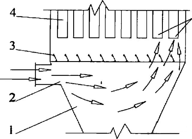
This kind of design can not achieve the goal of air distribution. The air flow is not uniform, in essence, the speed of each part of the air flow (i.e. dynamic pressure) is not uniform, and the local air flow speed is too high. The purpose of air distribution should be to eliminate the local high velocity and make the velocity of each part of the air flow tend to be uniform.
Therefore, the air distribution plate should be in the front of the air flow and placed in the air flow, so that the high dynamic pressure can be consumed. However, the air distribution plate shown in the figure above is located on the side of the dust laden air flow, which can hardly consume the high dynamic pressure of the air flow. Therefore, the dust laden air flow from the ash hopper flows to the plate wall at the far end of the ash hopper by inertia concentration, and flows upward along the wall face, carrying dust at a high speed to form a scouring on the filter bag, resulting in the damage of the first and second rows of filter bags near the far wall.
In order to avoid the above situation, it is suggested that the hopper air inlet should not be used as far as possible when the conditions permit. If the air inlet of the ash hopper cannot be avoided, the air distribution device shown in the figure is an alternative scheme, that is, a vertical air distribution plate is arranged in the ash hopper, which is placed in the dust laden air flow, so that it faces the dust laden air flow in the front, so as to weaken the high air dynamic pressure. At the same time, the vertical air distribution boards are different in length and length, which are arranged in steps, so that the dust gas is evenly distributed and the pixels flow. Time proves that this device can effectively avoid the scour of the dust air flow on the filter bag

